検索ボックス
検索フォーム
How to use HB-type products
What's the most important thing to keep in mind when using a HB-type product?
Safety is always important. Always double-check to confirm that the test motor and torque measurement component are set up correctly. Check the coupling mounting screw for tightness before running the motor. If the coupling is not secure, it can fly off during measurement. Special care is required with metal couplings. Make sure the setscrew is firmly tightened to prevent injury and accidents.
We're concerned about the exposed rotating parts of the instrument used on our production lines.
We recommend installing a safety cover (available as an option) to house coupling sections.
Can calibrations be performed by the user?
Yes. We provide a calibration jig with the measurement component of each torque meter.
The user can perform zero-adjustments for torque value and adjust and confirm ratings.
Send the product to our company for calibration if you need a calibration certificate.
Please describe how to calibrate the HB measurement component for torque value.
We use the static calibration method, which involves attaching a calibration bar to the shaft on the torque measurement component and suspending a weight from the calibration bar. This calibration method is based on the principle of moments drawn from physics. When you hang the provided weight on the indented section at the end of the calibration bar, the instrument should indicate the rated torque. If not, adjust the dial so that the instrument indicates the rated value.
How often should I perform calibration using the calibration weight?
Since calibration values obtained by using a calibration weight don't usually fluctuate over short periods, there's no need to perform calibrations after each measurement. We recommend calibrating once a week or once a month, based on conditions of use.
How can I remove (degauss) remanent magnetism?
Remanent magnetism can be removed by exciting the brake and slowly decreasing the excitation level to zero while rotating the shaft at 100 r/min or faster using a motor or similar device. For easier but less thorough degaussing, attach the calibration bar to the shaft and slowly decrease the excitation level to zero while turning the shaft.
Can you explain how to set measurement conditions to measure speed-torque characteristics?
Sugawara's speed-torque measuring instruments use a moving operating point system. With this system, the user sets the operating point (point at which load and speed are balanced) for the test motor. The user enters measurement conditions in the setting screen of the controller software. For example, the user can set the load to be applied to the motor and obtain measurements from 0 to 10 N·m in 0.5-N·m increments (= 0, 0.5, 1, 1.5..., 10.0 N·m) (torque control). It's also possible to control the load torque to achieve a specific rotation speed (speed control). This is a closed loop system that feeds back the measured torque value for control operations, eliminating the need for the user to set various parameters-P (proportional control), I (integral control), and D (differential control)- required for PID control with a sweep-type measuring instrument. This sidesteps the awkward procedure of setting parameters that typically requires extensive user experience.
Can you explain how to perform a life test by applying a constant load?
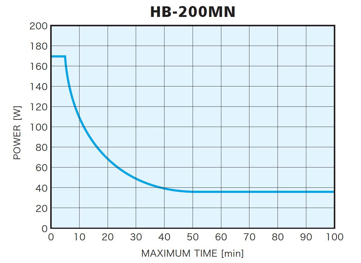
Set the control unit to manual mode, enter the load value, and run the test. To prevent damage to the equipment, make sure the motor output doesn't exceed the input absorption limit of the HB measurement component. See the operating manual for input absorption characteristics charts for each measurement component.
Is it possible to measure the relationship between the torque and rotation speed of a three-phase motor while measuring electric power, voltage, and current values on the inverter input side and output side?
Yes. You can do this by combining the PC-EMA1-W2S/PC-EMA1-W3S software for the PC-SAA2/PC-SAA3 motor analyzer and the WT1600/WT1800 digital power meter manufactured by Yokogawa Electric. You can mount up to six elements, allowing measurements-for example-of three voltage, three current, and three electric power values on the input side of a three-phase input inverter and three voltage, three current, and three electric power values on the output side to a motor, as well as the input/output efficiency. This gives you the relationship between the torque and rotation speed of a three-phase motor.
I'm planning to add a HB measurement component. Can I use one control unit for multiple measurement components?
You can use the optional EMA-CB measurement component switcher box to connect and select from four torque measurement components.
Can I ask Sugawara to calibrate our instruments?
Yes. Send your measuring instruments to our company to have them calibrated at our Kawasaki City factory.
Can I use Microsoft Excel to process the data obtained?
Yes. The data is saved to CSV files.