検索ボックス
検索フォーム
External drive signal for a stroboscope
How can I use an external signal to operate a stroboscope?
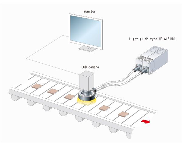
For normal use, the internal oscillator of a stroboscope is used to illuminate the flashlamp. If you are using stroboscopes as light sources for video camera systems used in automated inspection lines in factories that manufacture bottles, cans, or other such objects, you can use signals from external devices like photoelectric pickups to trigger stroboscope flashes. We call these signals external synchronization signals. Stroboscopes that use external signals can be used across a wide range of applications, including high-speed automatic inspections for factory automation, recording high-speed phenomena such as the destruction/explosion of objects, and video recording for highway traffic management.
* Important note
Specifications for Sugawara's stroboscope products can vary somewhat for certain models. Check the specifications document or other materials to ensure correct use of products. (Problems due to incompatible external synchronization signals are common.) If you have any questions concerning specifications or other issues, please don't hesitate to contact our sales office. Our technical team will answer your questions.
Please describe the types of external signal used to operate a stroboscope.
Transmission-/reflection-type photoelectric pickups, proximity switches, and electromagnetic pickups are commonly used to synchronize strobe flashes with the motion of a moving object. Three types of external synchronization signals can be sent from sensors to stroboscopes: voltage signals, current signals, and contact signals.
What is a voltage signal?
A voltage signal is a signal that uses a change in voltage in the signal line to trigger a certain function. See the following explanation on voltage waveforms and signal polarities.
Positive pulse wave (POS)
The sharp rise in voltage triggers the stroboscope.
Negative pulse wave (POS)
The sharp drop in voltage triggers the stroboscope.
Rectangular wave, square wave
High voltage and low voltage alternates at a frequency of almost 1:1. A change in voltage to either high or low is used to trigger the stroboscope.
TTL level
This type of signal is used with general-purpose logic ICs.
As with the rectangular wave described above, this signal uses a change in the voltage to high or low to trigger the stroboscope. The low voltage level (LOW level) is between 0 and 0.8 V, while the high voltage level (HIGH level) is between 2.4 and 5.0 V.
Sine wave
This type of signal is typically used with a ready-made oscillator or for observations of the condition of a vibration generator. This type of signal is unsuitable as an external synchronization signal for a stroboscope due to the gradual change in voltage and the difficulty of determining the signal timing. If you plan to use this signal, you should undertake thorough verification in advance.
What is a current signal?
A current signal is a signal that uses a change in current in the signal line to trigger a certain function. Current signals suppress the effects of external noise. You can use a photocoupler input to isolate the device generating external signal from the stroboscope.
Current ON signal
The sharp rise in current triggers the stroboscope.
Current OFF signal
The sharp drop in current triggers the stroboscope.
What is a contact signal?
A contact signal is an open/closed signal from an external electronic contact or mechanical contact, which is input to trigger a stroboscope.
Open contact signal (BREAK)
In the case of an electronic contact, every change in the open collector from ON to OFF triggers the stroboscope. In the case of a mechanical contact,* every change in the contact from closed to open triggers the stroboscope.
Closed contact signal (MAKE)
In the case of an electronic contact, every change in the open collector from OFF to ON triggers the stroboscope. In the case of a mechanical contact,* every change in the contact from open to closed triggers the stroboscope
* The opening or closing of a contact in a mechanical contact like a switch will generate chattering. Note that certain devices may respond to this chattering and operate erratically.
Why is there a signal delay?
Ideally, when we use an external synchronization signal to operate a stroboscope, the stroboscope should flash at the exact moment an external synchronization signal is input to the stroboscope. However, in actual use, there is a slight delay. At our company, this delay is called the flash delay time. The flash delay time can vary significantly depending on the xenon flash tube (internal trigger tube, external trigger tube) used in the stroboscope. It can also vary slightly depending on the type of external synchronization signal used.
Since photocoupler input is used with a current signal, the flash delay time is longer when we use a current signal than other signal types. In the case of a contact signal, the response time may be restricted to prevent errant operations caused by chattering. Voltage signals provide better performance with respect to flash delay times.