HB Series Dynamometers
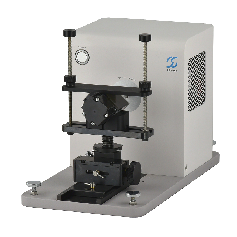
HB series are the successors to the TA/TB series hysteresis brake dynamometers, which have demonstrated many years of reliable operation. The torque accuracy has been improved to ±0.1% of the rated torque, and the maximum rotation speed has been significantly improved to 60,000 rpm in the lower torque models. Two types of high-resolution encoder options are available, which enable ultra-low speed measurements of 10 rpm and 5 rpm. We offer a lineup of 13 models with rated torques ranging from 5 mN·m to 50 N·m, including short plate models and models for temperature chambers.
Motor Testing Equipment(PDF: 4.6MB)
Torque Dynamometer (PDF: 3.3MB)
Reliable hysteresis brake
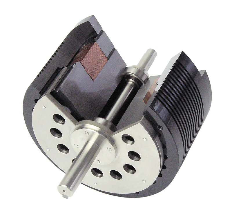
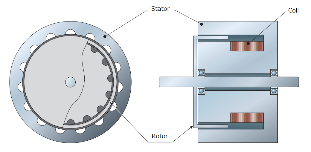
A hysteresis brake is structured to rotate a rotor made of high permeability magnetic material inside an air gap containing a magnetic field formed by a cog-wheel-shaped stator. The magnetic flux flowing in the stator passes through the rotor, creating magnetic friction between the rotor and the stator, and acting as a non-contacting brake. This magnetic friction is proportional to the strength of the magnetic flux penetrating the rotor, and the strength of this magnetic flux can be adjusted by changing the strength of the exciting current applied to the coil. Therefore, a hysteresis brake makes it easy to adjust the braking force regardless of the rotation speed of the rotor.
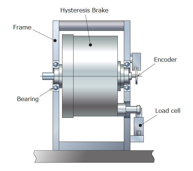
The brakes of HB series dynamometers are retained by bearings on the equipment frame. When the rotor is turned by the motor under measurement and braked by magnetic friction with the stator, a reaction force is generated on the stator and the stator tries to rotate. This reaction force is detected by a load cell as the brake torque. Since the rotational moment acting on the stator is detected in an extremely static fashion, it is less susceptible to vibration than methods that involve detecting torque on a rotating shaft, and results in a stable detection method that is suitable for high-speed rotation.
Main features
- In our highly reliable hysteresis brake, which is supported by 50 years of experience, we have reduced the gap between the rotor and stator and minimized the inertia moment of the rotor, resulting in better torque control performance and less vibration during rotation.
- The torque accuracy is ±0.1% of the rated torque (accuracy of the system including DM5000 Controller, after calibration) in all the 13 models.
- World-class high-speed rotation: 60,000 rpm in three models with rated torques of 50, 100 and 200 mN·m, and 50,000 rpm in the 500 mN·m model.
- An optional rotary encoder for the measurement of extremely low speeds: 10–10,000 rpm (600P/R) and 5–5,000 rpm (1200P/R).
- Uses the well-established MMJ-series motor mounting jigs, although custom-made jigs can also be made.
- For seven models, ranging from HB-50MN (rated 50 mN·m) to HB-5N (rated 5 Nm), short plate models and models for temperature chambers are available as standard.
Main specifications of HB series Dynamometers
| Model | Max. torque | Max. speed (rpm) (∗1) | 5 minute power rating (W) | Continuous power rating (W) | Standard motor jig set |
|---|---|---|---|---|---|
| HB-5MN | 5 mN・m | 40,000 | 7.5 | 1.5 | MMJ-7C |
| HB-10MN | 10 mN・m | 40,000 | 15 | 3 | MMJ-7C |
| HB-20MN | 20 mN・m | 40,000 | 30 | 6 | MMJ-7C |
| HB-50MN | 50 mN・m | 60,000 | 75 | 15 | MMJ-7C |
| HB-100MN | 100 mN・m | 60,000 | 120 | 25 | MMJ-7C |
| HB-200MN | 200 mN・m | 60,000 | 170 | 35 | MMJ-7C |
| HB-500MN | 500 mN・m | 50,000 | 300 | 60 | MMJ-9C |
| HB-1N | 1 N・m | 30,000 | 400 | 80 | MMJ-9C |
| HB-2N | 2 N・m | 30,000 | 900 | 400 | MMJ-10C |
| HB-5N | 5 N・m | 20,000 | 1,500 | 300 | MMJ-10C |
| HB-10N | 10 N・m | 12,000 | 3,000 | 700 | MMJ-12B |
| HB-20N | 20 N・m | 12,000 | 6,000 | 1,200 | MMJ-12B |
| HB-50N | 50 N・m | 7,000 | 12,000 (∗2) | 4,000 | (∗3) |
(∗1) All the models have two kinds of low-speed encoder versions, 600P/R type (10-10,000 rpm) and 1200P/R type (5-5,000 rpm).
(∗2) 3 minute power rating for HB-50N
(∗3) Customized jigs are available.
Specifications and power absorption curves
MMJ-series motor mounting jigs
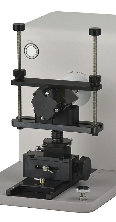
MMJ-series motor mounting jigs have an adjustment function for centering the motor and measurement axes. Four models are available for twelve measurement units ranging from HB-5MN to HB-20N. Since the surface of the V block of MMJ on which the motor under test is placed is designed to be parallel with the shaft of the dynamometer, the shafts of the motor and dynamometer will be parallel when they are simply mounted on the V block. As a result, alignment is easy to achieve.
Calibration
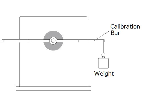
Optional calibration bar and weight are needed to calibrate the dynamometer. Attach the calibration bar to the shaft as shown in the figure, and suspend weight from the groove in the calibration bar as instructed by the dedicated software. There is no need for troublesome volume adjustments because the zero adjustment and CW/CCW torque adjustment are performed in the dedicated software.